Introduction
Selecting a pressure sensor for a new product design requires more than simply matching a pressure range. In real engineering environments, the wrong sensor choice often leads to integration issues later in development—unstable readings, signal incompatibility with the control electronics, installation constraints, or long‑term reliability problems caused by temperature, vibration, or moisture.
For OEM buyers, sourcing managers, and design engineers, the goal is to narrow down the sensor selection early while ensuring the device will integrate smoothly into the final product. A structured selection process helps avoid redesign work and reduces risk during qualification and production.
This guide explains the practical decision process used by many engineering teams when selecting pressure sensors. It focuses on the key factors that typically determine suitability in OEM designs: pressure type, pressure range, output signal, supply voltage, media compatibility, package and installation style, accuracy requirements, and environmental conditions.
Step 1: Identify the Pressure Type
The first step is to determine what type of pressure measurement the application requires. Pressure sensors are designed to measure pressure relative to different references.
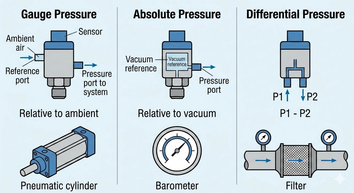
Common pressure measurement types
- Gauge pressure – measured relative to ambient atmospheric pressure
- Absolute pressure – measured relative to a vacuum reference
- Differential pressure – measures the difference between two pressure points
Each type serves different engineering purposes.
For example:
- Pneumatic control systems typically use gauge pressure
- Altitude or barometric measurements require absolute pressure
- Flow measurement across filters or orifices often requires differential pressure
Selecting the wrong pressure reference type can produce misleading readings even if the pressure range appears correct.
Step 2: Define the Actual Pressure Range
After identifying the pressure type, determine the real operating range of the system.
This requires more than identifying the nominal working pressure. Engineers should consider:
- Normal operating pressure
- Maximum system pressure
- Possible transient spikes during startup or valve switching
- Overpressure conditions
A sensor operating continuously near its maximum range may suffer from reduced measurement headroom or long‑term stress. Conversely, choosing an excessively large range may reduce effective signal resolution.
A common approach is selecting a sensor range that comfortably covers normal operation while leaving margin for transient pressure events.
Consider dynamic pressure behavior
Many real systems—such as pumps, compressors, or pneumatic valves—do not produce steady pressure. Pulsation and rapid pressure changes should be considered when selecting the range.
In early development stages, prototype measurements or historical data can help define realistic pressure limits.
Step 3: Choose an Output Signal Compatible with the Electronics
The pressure sensor output must integrate easily with the control electronics of the device.
Common output formats include:
- Analog voltage signals
- Digital communication interfaces
- Ratiometric analog outputs
- Bridge or millivolt‑level outputs
The appropriate output depends on the architecture of the system controller.
Questions engineers should consider
- Will the signal connect directly to a microcontroller ADC?
- Does the system require digital communication for noise immunity?
- Are long cables used between the sensor and controller?
- Is signal conditioning already implemented on the board?
Choosing an output that matches the existing electronic architecture reduces the need for additional signal conditioning or redesign work.
Step 4: Verify the Available Supply Voltage
Supply voltage requirements can significantly narrow the sensor options.
Before finalizing the selection, confirm:
- The voltage rail available in the system
- Allowed voltage variation
- Power consumption limits
- Startup voltage conditions
Some sensors produce outputs that scale with supply voltage. In such cases, the measurement electronics should account for this relationship when interpreting the signal.
For battery‑powered devices or compact embedded systems, low power consumption may also be an important consideration.
Step 5: Confirm Media Compatibility
The medium being measured is a critical factor in pressure sensor reliability.
The sensor must tolerate the fluid or gas that comes into contact with the sensing interface. Engineers should consider:
- Gas vs. liquid measurement
- Presence of moisture or condensation
- Chemical compatibility
- Oil, fuel, refrigerant, or other fluids
- Potential contamination or particles
Even when the sensing element itself is protected by a diaphragm or isolation structure, the materials used in the pressure port and housing must be compatible with the application medium.
Media compatibility is especially important in applications such as:
- Fluid control systems
- HVAC and refrigeration equipment
- Water management systems
- Industrial process equipment
- Medical or laboratory devices
When compatibility is uncertain, consulting detailed material specifications is recommended before finalizing the design.
Step 6: Select the Package and Installation Style
Mechanical integration is often overlooked early in the design process, but it strongly affects manufacturability and reliability.
Pressure sensors are available in various package formats depending on the intended installation method.
Important considerations include:
- PCB mounting versus threaded process connection
- Available installation space
- Tubing or manifold interface
- Sealing requirements
- Assembly process in production
A sensor package that fits easily within the mechanical layout can simplify both assembly and servicing.
Mechanical stress considerations
Mechanical loads from tubing or connectors can sometimes transfer stress into the sensor package. Ensuring the installation design minimizes these stresses can improve long‑term stability.
Step 7: Evaluate Accuracy Requirements
Accuracy specifications often include several components rather than a single value.
These may include:
- Linearity
- Hysteresis
- Repeatability
- Offset error
- Temperature influence
- Long‑term drift
For many OEM applications, the most important question is not the highest possible accuracy but the accuracy level required for the intended function.
For example:
- A safety monitoring system may require consistent threshold detection
- A control loop may prioritize repeatability
- A measurement instrument may require tighter overall accuracy
Understanding the role of the pressure measurement in the system helps determine appropriate accuracy requirements.
Step 8: Assess Environmental Conditions
Environmental factors strongly influence long‑term sensor performance.
Typical environmental considerations include:
- Operating temperature range
- Thermal cycling
- Humidity and condensation
- Shock and vibration
- Dust or liquid exposure
- Electrical noise
Sensors used in outdoor equipment, mobile machinery, or industrial environments may experience conditions that differ significantly from laboratory tests.
Evaluating these conditions early helps ensure the selected sensor can operate reliably over the full life of the product.
Common Selection Mistakes
Even experienced teams sometimes encounter delays caused by early assumptions. Typical mistakes include:
- Selecting the wrong pressure reference type
- Choosing a pressure range without considering spikes
- Ignoring output compatibility with system electronics
- Overlooking supply voltage constraints
- Assuming media compatibility without verification
- Selecting a package that complicates installation
- Over‑specifying accuracy requirements
- Underestimating environmental stress
Avoiding these issues early can significantly reduce development time.
Typical Matching Models from Reliavatech
Different pressure sensing technologies are suited to different application requirements. During early evaluation, engineers often compare several representative sensor types.
Examples include:
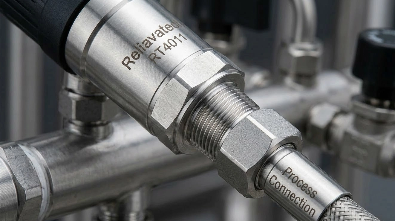
- RT4011 – ceramic pressure transmitter for gauge pressure measurement with threaded process connection

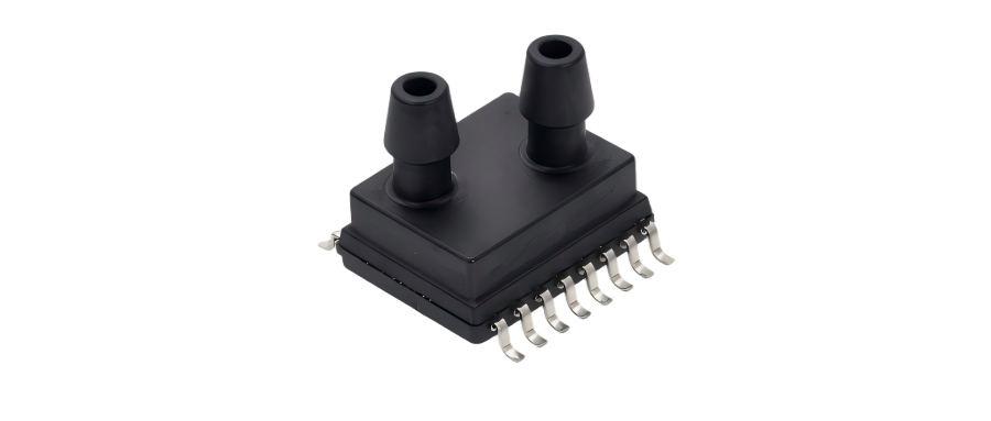
- RP3112 – MEMS differential pressure sensor designed for small pressure ranges and digital output integration
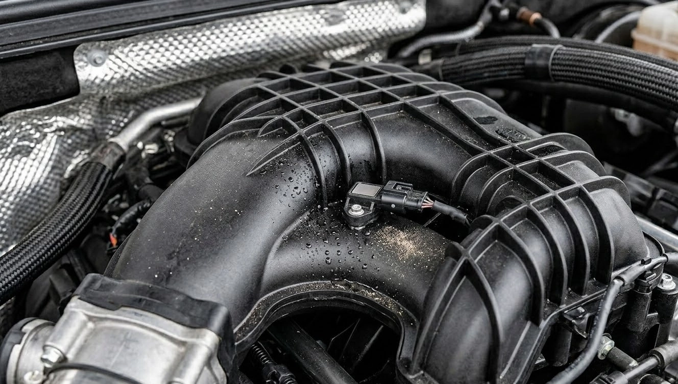
- RP3311 – MEMS absolute pressure sensor commonly used for automotive intake manifold pressure measurement (MAP), suitable for monitoring air pressure in engine intake systems
These models illustrate different measurement approaches and integration styles. The appropriate selection depends on the specific pressure type, range, interface, and mechanical requirements of the application.
FAQ
How do I determine the correct pressure range?
Measure or estimate the full operating range of the system, including startup conditions and pressure spikes. Choose a sensor range that comfortably covers these values.
When should I use a differential pressure sensor?
Differential pressure sensors are commonly used when measuring pressure drop across filters, valves, or flow elements.
Is higher accuracy always better?
Not necessarily. The required accuracy depends on how the pressure measurement is used in the system. Many applications prioritize stability and repeatability over extremely tight accuracy specifications.
Conclusion
Selecting a pressure sensor is a system‑level engineering decision. By evaluating pressure type, operating range, signal interface, supply voltage, media compatibility, installation method, accuracy requirements, and environmental conditions, engineers can significantly reduce the risk of integration problems later in development.
A structured selection process also helps ensure that the chosen sensor aligns with both technical requirements and manufacturing constraints.
Contact Reliavatech for Selection Support
If you are evaluating pressure sensors for a new design, the Reliavatech engineering team can assist with model selection and technical documentation. Contact us for detailed specifications or guidance in selecting a suitable pressure sensor for your application.